...Amazing...
|
H< HBE PROJECT > |
|
Don’t expect to find superb models that would make you dream...No ! This is only some research on rotary wings home made in order to minimize energy consumption. The result complies not to some aesthetic shaping but to a requirement specification to attempt world records in duration... Another way to dream ! |
| n |
| h |
| HBE project birth |
|
Being by nature very inquiring about energetic problems, I thought that something could be done about RC (Radio Controlled) helicopter models. At this time, early 1997, the state of the art in flight duration of electric helicopters on the market was about 6 to 7 minutes ; this being done in hover with 1.7Ah NiCd battery cells. My idea was then to check whether it was possible to bring a significant improvement. This work would do for any power plant : electric motors and piston motors. The HBE project , was then born. |
|
HBE Hélicoptère Basse Energie (low energy helicopter) |
|
Discussing about what I had in mind with a friend of mine, Pierre Hermet, engineer, he came very nicely to this idea and started the job on the go. He could therefore exercise his real talents of theorist. Although this domain was far from our professional activities, he went right in the matter, building up a rotary wing mathematical model on his PC. I was impressed by the realistic results of his model so we needed to check that with reality. Our work method was then born, consisting in matching theoretical model (simulator) and experimental result to select the right way in our future developments. Not being experts in aerodynamic matters, it was necessary to start from the sources and almost discover all the problems. So we came to the idea to work out a test bench to drive a rotary wing and to measure the lift and the torque at a given spinning speed and pitch angle. The first bench, too simple, provided a bad speed control and enabled only to compares relative performances between blades (blades from the market at that time). We realized it was then required to perform an accurate speed and pitch control in order to get a significant comparison of the results with the theoretical model. |
|
|
 |

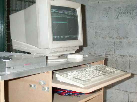
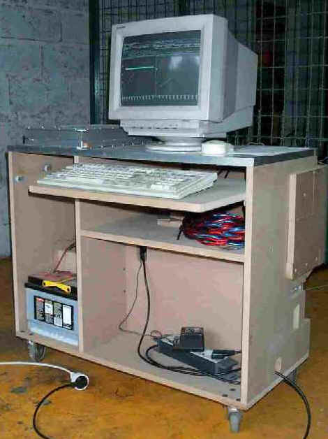
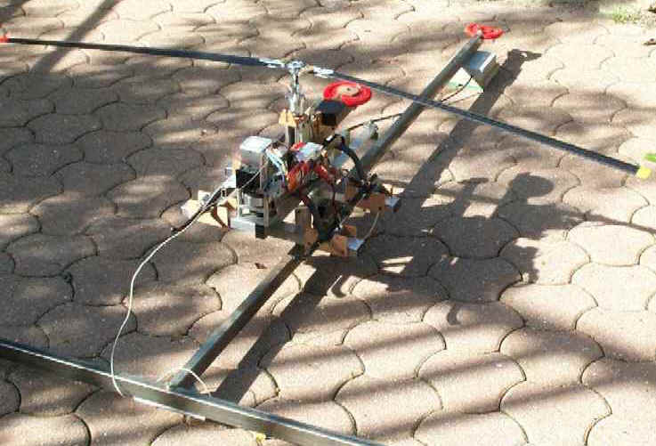
| Building up a test bench for rotary wing |
|
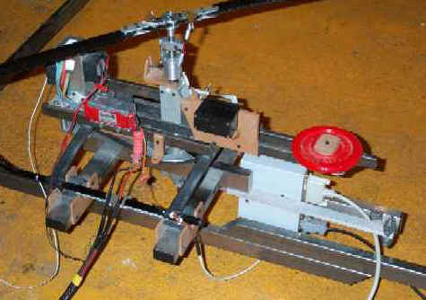
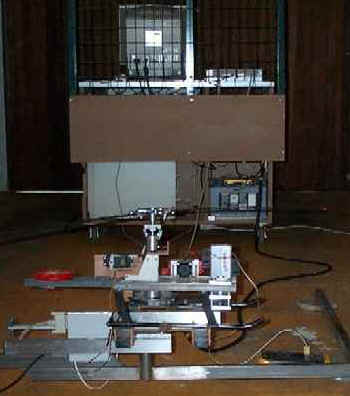
The second bench is divided in a control unit and a drive unit. The control unit is based on a computer (PC 386) and an interface cabinet (designed and home made) with the drive unit via a control cable and a power cable. On its side, the drive unit is based on a framework that includes a brushless motor with its controller, mechanical reducer, clutch, 4 blade rotor head and its collective pitch control servo (no cyclic control) ; in addition, the sensors dedicated to lift, torque, rotor speed, motor current/voltage are also included. The pitch is designed to be adjusted by steps of 1/10 of degree and memorized in tables as any other configuration parameters. The rotor speed is servo controlled within a few rpm's. For each measurements an hundred of samples are picked up and averaged. The complete bench insured a good reliability in the measurements which are made either on ground effect (IGE) or out of ground effect (OGE) using solid legs to rise up the drive unit. The software (made by my son Vincent) enables the configuration of the bench, the programming of automatic measurement sessions and to view the real time tracing of « lift to speed » « torque to speed » graphics on the screen. |
 |
|
|
|
|
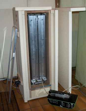
| Aluminum blade making |
|
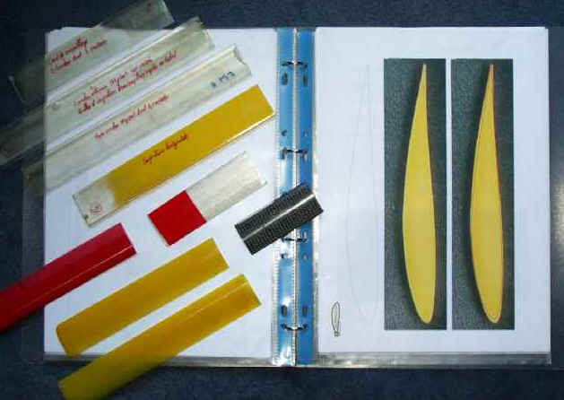
Doing measurements on blades coming from the market is good, but making our own blades to our own requirements is much better. A solution that doesn’t require industrial means had to be found. Taking an aluminum sheet folded on itself was the basic idea, closed at tip and trailing edges and then injected with epoxy resin. This technique is quite efficient and provides a high technology added value. However this can be reached under the condition of implementing an adequate set of tools. This one includes essentially a multifunction folding/rolling device, a sort of plane used to machine the wooden blade templates, a mounting press and a warming chamber for resin injection and hardening. Thanks to that different blades were made with symmetrical airfoils (NACA) or cambered (Eppler) with rectangle or trapeze shapes, plane or twisted for right or left rotation. In airfoil analysis, we got some help from a bank of airfoils UIUC (http://amber.aae.uiuc.edu/~m-selig/ads/coord_database.html) and from the Web site of Martin Hepperle (http://beadec1.ea.bs.dlr.de/Airfoils/calcfoil.htm) for airfoil computation. |
 |
 |
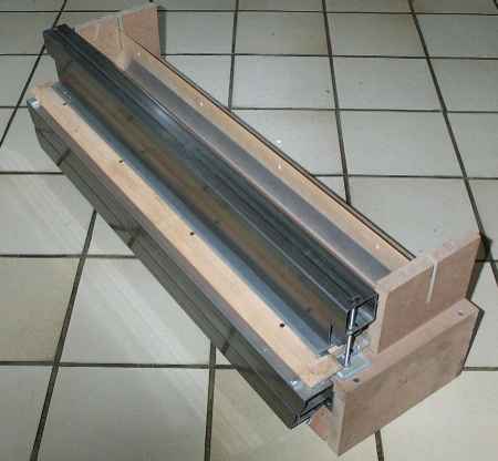 |
Home made tools to manufacture the blades
| Measurement results |
|
Computation and experimental results turned out to be very close which enabled us to undertake the rotor energetic optimization with the simulator. For a given lift and rotor diameter, airfoil choice, chord and rotor speed are the most significant variables of this optimization. The biggest difficulty stays in the drag estimate at very low Reynolds number (Refer to <the helicopter blade>). Later on we have improved the simulator including the rotor conicity and the blade distortion (flexion, twist) upon centrifugal and aerodynamic constraints. We now have acquired a good mastery of the subject which enables us to simulate the rotor within an accuracy of a few percent. Of course some coefficients are still empirical but they are not most significant. Unfortunately we cannot simulate correctly the tip vortex as this can be done in a research center, the ONERA (Office National de la Recherche Aéronautique) for instance. It might remain a potential gain of a few percent using optimized tips but no way is clearly open in this domain. |
|
|
Comparing our blades to conventional ones in very similar conditions (diameter, speed) we estimate the gain in torque and power to about 22% in favor of our blades (of course !). If you adopt such blades on a conventional helicopter the motor will be significantly relieved and adjustment will be easier (less power, easy cooling). Our faithful 30 Baron testifies of it.
|

|
Four bladed rotors have also be tested but this configuration degrades the energetic efficiency due to the wake effect interfering within blades. It is best adapted for heavy disk load as a compact solution. |
 |
|
dear 30 Baron as a witness |
| HBE_00 prototype |
|
HBE_00 Features |
| Rotors | . |
| Rotor : number / diameter | 2/1500mm |
| Blade chord | 34mm |
| Airfoil | Eppler 201 |
| Conicity | 2,7degree |
| Rotor speed | 900rpm |
| Tip speed | 71m/s (255km/h) |
| Centrifugal force | 39,5kg |
| Fuselage | . |
| Distance between rotors | 1330mm |
| Rotor overlap | 11,3% |
| Front rotor height in horizontal position | 460mm |
| Rear rotor height in horizontal position | 515mm |
| Fuselage length | 1560mm |
| Wheel base | 1165mm |
| Rear track | 580mm |
| Power plant | . |
| Motor | Aveox 1817/4Y |
| No load voltage | 40V |
| Battery capacity | 2 A.h |
| Motor speed | 12270rpm |
| Intermediate shaft speed | 4160rpm |
| Mass | . |
| Disk load | 2kg/m2 |
| Blade mass (aluminum) | 460gr (4x115gr) |
| Battery mass (4x16 cells) | 3788gr |
| Gross weight in run order | 6943gr |
|
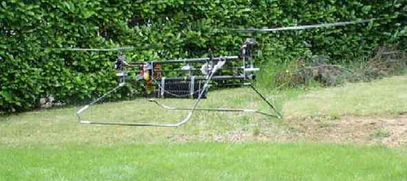
The test bench and the blades were a good basis but we wanted more investigations. It was then high time to make our own experience with a flying prototype before going to the record attempt. The tandem configuration was decided because we thought (and we think the same today) it was the best formula considering energetic efficiency. May be it’s not very significant, let’s say 10% compared to a similar single rotor of same swept surface. It was also the occasion to fight against major difficulties that we had underestimated (now we know...). It was then required to compute the complete energetic chain from the battery to the rotor, including the controller, the motor and the mechanics. |

|
The design and building of the prototype took me about 6 months, full time. The fuselage structure is isoplane with balsa spacers within two 4/10 carbon sheets. This structure is very light and stiff even in excess compared to the need. |
|
The loading unit used also to powerfeed HBE-00 during first flights |
For the first testing of HBE_00, a three axis balance was implemented to stand the machine, able to move free on its 3 axis. Unfortunately we were unable to establish effective conclusions on the control/stability aspects with this balance and we rather lost our time. So we went to the flight platform. We made current/voltage measurements in hover (powerfeed link) and the results greatly confirmed what we had anticipated by computation. It was at this time, when I was making the prototype, that my friend Jacques Boyer came into the project as test pilot and technical adviser. Thanks to its strictness toward himself (and others...), he brought the required breath for a rapid progress in the project. We remember a great day with Jacques piloting : HBE_00 took off at 6.9kg gross weight with 2 x 32 2Ah cells and made a 23 minutes 40 seconds hover on the 9th of June 1999. This flight could not be registered because the machine did not comply to the FAI regulations.
|

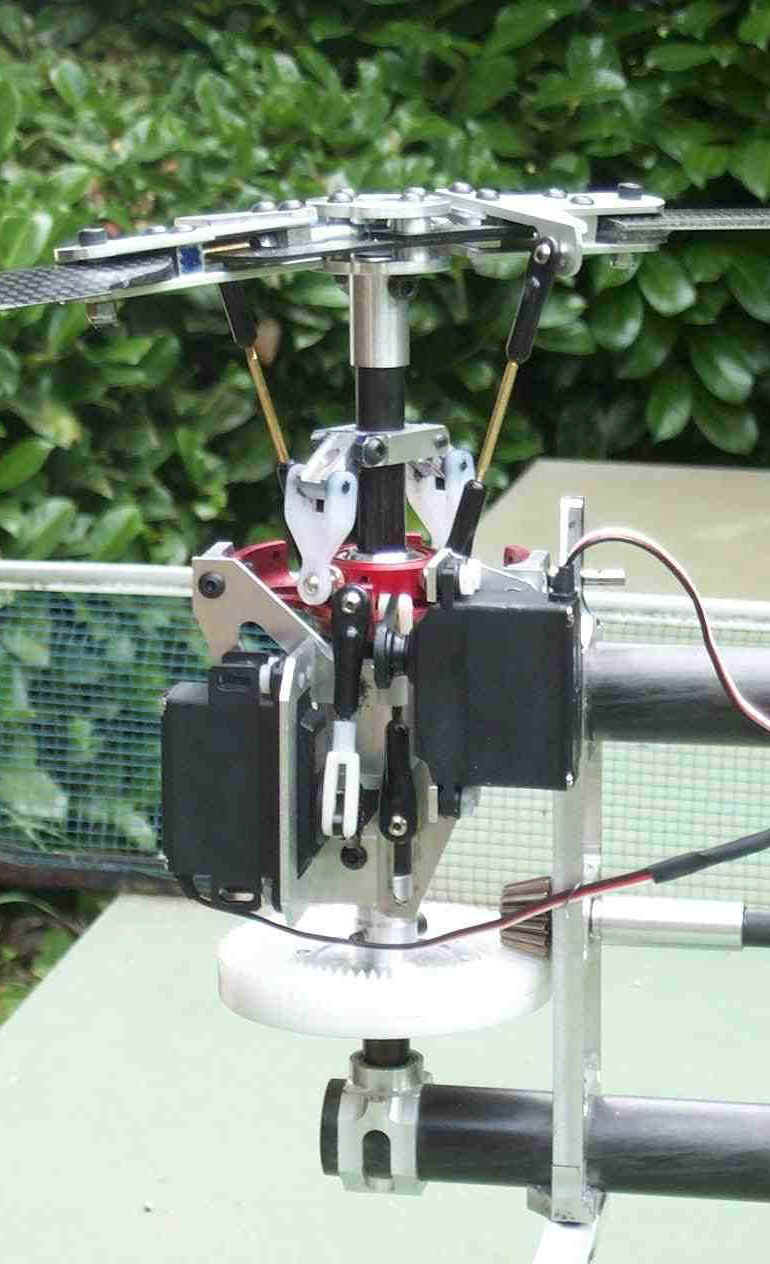
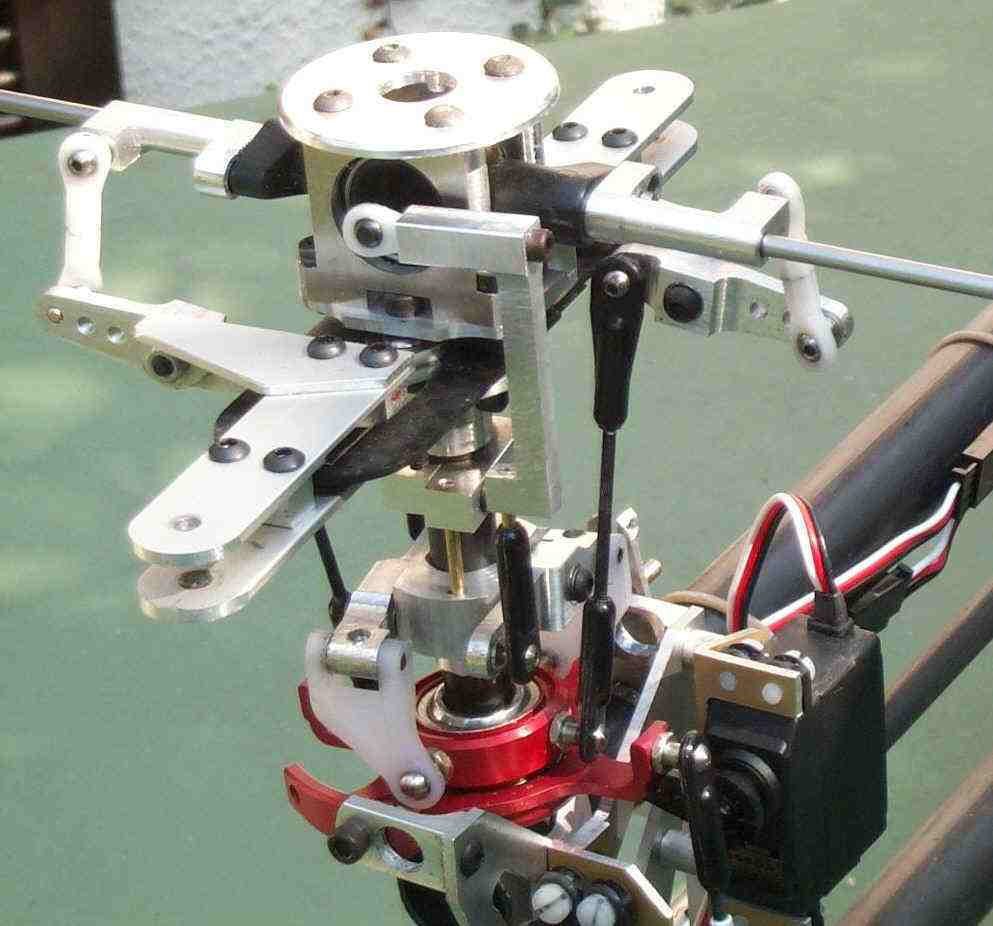
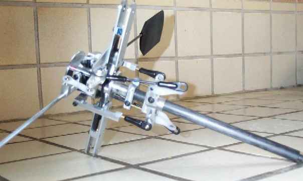
| Articulated rotor head (flapping) |
|
The first hover trials were critical most of all because we had only one gyro in pitching, no Bell bars and hard rotor heads. We were on the look out of the lightest turbulence... With this rotor head the machine had a regrettable tendency to slide fast and flat sideways, yielding practically no visual information. We then decided to design our own articulated rotor head from a ball principle discarding all conventional ball bearings. With this principle the blade holder is free to move vertically and horizontally , the pitch angle being strictly controlled. The benefit of it might be compared to change from a car with hard suspensions to another one with soft independent suspensions. |
|
|
|
|
|
|


|
Trimming and flight testing have driven us to remove the blade holder stops (to stand the blades when the rotor stands still) and to adjust the elasticity of the carbon blade. We also extended the angle travel capability of the blade holders and made it symmetric providing a significant improvement in terms of stability and turbulence resistance. This rotor head first tested on our 30 Baron, then on HBE_00 gave out excellent results preventing the machine from sliding flat and improving turbulence resistance. In addition, however, a yaw gyro became necessary to make piloting easier. From this time on, this rotor head was implemented with several improvements and now we estimate to reach a stable version. |
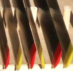
| Glass/Carbon blade making |
|
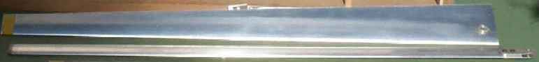
The aluminum blades are very good and particularly resistant to twist but they don’t comply with FAI that required to fly without metal blade. After laborious trials to specify the process, the first glass fiber blades were born but they were not stiff enough in twist and their surface was not perfect ; it was necessary to improve injection conditions and also to increase the number of layers. |
|
|
It is in fact difficult to get a stiff blade when the chord is in the range 30 to 40mm with a relative thickness of 12% for a rotor diameter of 1.4m. |
|
A fiber glass sample of a blade, empty and very light but not hard enough in twist. |
 |
 |
When we got a fine making, the 30 Baron had again to participate to the trial. The result came immediately : as the blades have high lift and low drag, the helicopter got overpowered with an impressive ability in vertical climbs, smoothness and accuracy of control were also significantly increased compared to conventional blades. The process was then improved to finally work out a glass/carbon composite (more carbon than glass) with a perfect finish and above all with a flexion/twist features particularly impressive. |

|
After having made about 14 pairs of composite blades for different applications, the process can be considered mature. Following two accidents (we were not always successful...) it turned out they are practically indestructible, only a few scratches. |
|
|
 |

All
our prototypes are now enhanced with these blades.
|
For the different types of blades, static trials to centrifugal forces have been done with a dedicated equipment. |
| HBE_E & HBE_T prototypes |
|
After
having trimmed HBE_00 to the best (wrong impression because hovering in
turbulence was not enough tested), it was exciting to carry on the way
and to aim at the FAI duration record. F5C regulations can then be simply
summarized :
|
|
h
|
| Rotors | HBE_E | HBE_T |
| Rotor : number / blades / diameter | 2/4/1,4m | 2/4/1,25m |
| Swept surface | 3 m2 | 2,35 m2 |
| Chord / airfoil | 31,4mm / Eppler 201 | 31,4mm / Eppler 201 |
| Centrifugal force | 22 kg | 17 kg |
| Conicity | 3 degree | 3,2 degree |
| Tip speed | 62m/s (223km/h) | 54m/s (195km/h) |
| Rotor torque (altitude 1 rotor diameter) | 1,15Nm at 4,9kg | 1Nm at 4kg |
| Framework | HBE_E | HBE_T |
| Distance between rotors | 1225mm | 1225mm |
| Front rotor height (horizontal) | 410mm | 410mm |
| Rear rotor height (horizontal) | 450mm | 450mm |
| Framework | HBE_E | HBE_T |
| Distance between rotors | 1225mm | 1225mm |
| Front rotor height (horizontal) | 410mm | 410mm |
| Rear rotor height (horizontal) | 450mm | 450mm |
| Power plant | HBE_E | HBE_T |
| Motor type | Aveox 1514/4Y (brushless) | OS
FS26 Surpass
4 strokes |
| Rotor
speed
Intermediate shaft speed |
850rpm
3800rpm |
850rpm
3800rpm |
| OGE
(out of ground effect) power
(2 rotors) |
200W | 130W to 200W |
| Energy | Batteries
2 A.h
26,5 v no load voltage |
Main
tank (1,5l)
Auxiliary (0,1l) |
| Mass | HBE_E | HBE_T |
| Gross weight in operation | 4900gr | 2700gr up to 4100gr |
| Energetic weight | 2520gr (battery) | 1400gr (petrol) |
| Mass | HBE_E | HBE_T |
| Gross weight in operation | 4900gr | 2700gr up to 4100gr |
| Energetic weight | 2520gr (battery) | 1400gr (petrol) |
|
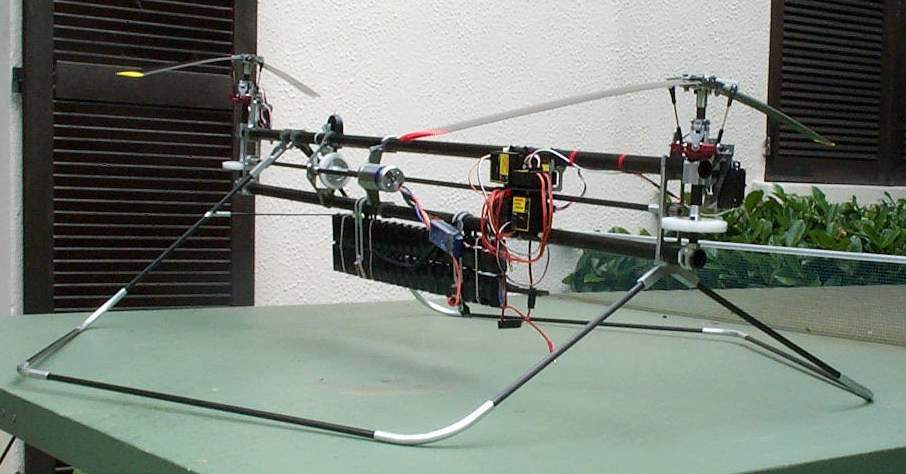
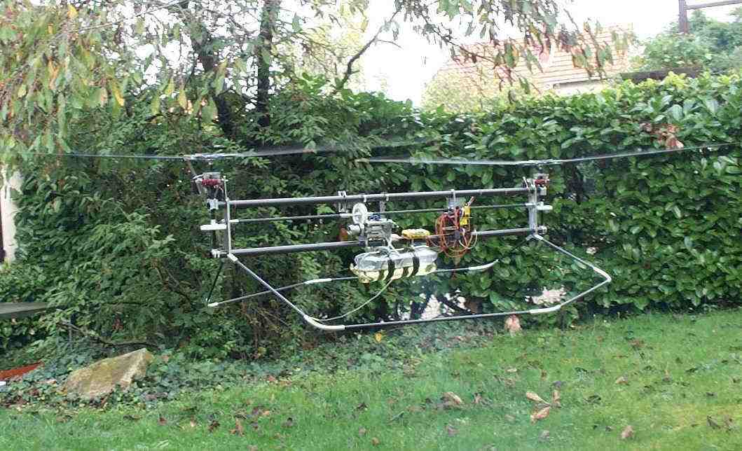
Starting from these regulations two tandem rotors have been undertaken and implemented, the difference being the power plant. The simplest machine was obviously the electric one : HBE_E. This tandem rotors powered by a brushless motor (Aveox 1415/4Y) weight only 2400gr without battery. This made possible to load the machine up to 2600gr so 2 batteries of 21 x 2Ah cells were installed. The rotors overlap lightly so that the swept surface is still in the FAI template of 3m2. The framework is made of two carbon tubes linked by several aluminum spacers ; this structure is simple and light but not very strong in twist. Every driving shafts (rotor shafts, intermediate shafts) are made of carbon tubes rectified to nominal diameter and reinforced in critical locations ; tests have been made to check whether they were able to stand the torque values in operation. |
|
HBE_E and its front mechanics (without Bell bar) |
|
 |
The making was not very critical except some problems arising from vibrations of the framework due to some resonance originating in the rear rotor. The landing unit also was not that much easy to design : several solutions have been tested before finding a satisfactory compromise. |
|
Every component is designed to be lightest possible and strong enough for mechanical constraints (including behavior to vibrations). As an example, a rotor head weight 60gr, a rotor shaft 11.5gr and a blade is 70gr. The power consumption on the battery is around 275W at 850rpm that is to say a motor current of 10 to 10.5A. Each rotor consumes 105W and the losses reach 65W distributed among the battery, the motor, the controller, the cabling, the reducers and the rotor overlap. The motor temperature raises up 40 to 45°C above ambient temperature after 20 to 25 minutes of continuous hover. |
 |
In operation HBE_T is lighter : around 4kg with 1.5l of petrol, that means more difficult about stability. The motor is a small 4 strokes OS_26 Surpass, a power of only 0.26HP being required in hover. |
| HBE_E et HBE_T flying |
|
The actual problems arose progressively during flight trials : the machine was very live with a major tendency to slide fast and flat. This has driven us to modify the rotor head and to revise the mass distribution and the gravity center position. But the most difficult problem was the turbulence resistance. From this point there were two possible actions: include Bell/Hiller bars on the rotor heads or implement a true 3 axis gyro stabilizer unit. |
|
In fact the two solutions were driven in parallel (big job) in order to establish a comparison : Bell bars on HBE_T against gyro stabilizer unit on HBE_E. At the same time our theorist was able to compute the rotor behavior under either a pilot control or an external disturbance. He also computed the tandem rotor behavior (induced effects) and in addition the servo control and Bell/Hiller transfer functions. This helped us considerably to understand the different problems and to take decisions. The major cause of instability to turbulence originates in the very low disk load (performance reason) that is 2 to 3 times lower than on conventional helicopters. This explains why HBE_T with Bell/Hiller bars is not so resistant as a standard single rotor. |
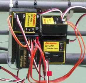
| Stabilization system |
|
HBE_E with its gyro stabilizer unit get a more stable behavior than HBE_T with its Bell/Hiller bar, that’s clear. |
 |
 |
Electronic solution against mechanical solution.
 |
Both side snapshots of the 3 piezo gyro (before modifications)
|
|
|
This is the reason why we have given up this solution and upgraded HBE_T with the gyro stabilizer unit. It is however difficult to compare HBE_E to a standard single rotor due to the very different disk load : HBE_E is liver but seems to be stuck on rails because of the servo control. The gyro stabilizer system is not made of plain components but has been deeply investigated to provide the required frequency band to the servo control chain. This electronic solution is still subject to changes but we do believe it is full of promises in the future, simpler and more efficient than the mechanical one (Bell/Hiller). It is even so efficient that the machine can still be piloted when it runs out of power at about 650rpm, the rotor being in stall conditions... |
| Record attemp |
|
The HBE project was lead to full success thanks to the efficient team operation and to our complementary nature added to a strong desire to reach the target. Our local club and the FFAM (French federation) were present the for management and support. |

|
from left to right
Claude Serres : judge Jean Claude Rey : official observer, president of the <Fédération Française d’AéroModélisme> (FFAM) Denis Genty : president of the club <La Croix du Sud> (Rambouillet) Jacques Boyer : pilot (FFAM license : 2092-AD, international license : FRA180664BJ) François Marcel : builder (FFAM license : 2091-AD, international license : FRA230242BJ) |
|
Finally the great day arrived : the record attempt took place the 8th of July 2000 at the field of Le Perreux en Yvelines. This was a wet and cloudy afternoon, the sun showing sometimes (weather conditions : 18°C temperature and wind in the range 5 to 20km/h). the duration of 21 minutes 41 seconds is considered as relatively low because the hover was higher than usual (one rotor diameter) to prevent risks from touching the grass. The piloting problem with HBE_T will be a major one because the record to overcome is of 5 hours 15 minutes and even if relaying each other is authorized, the first pilot has to stand the first hour at least. At the record time HBE_E had 11 hours flight. At the same time HBE_T had only 4 hours mainly dedicated to running in the motor ; a big amount of work remains to do on this machine although the target is for next year... |

| Documentation |
|
All along these three year of work, the measurement and trial results have been registered, same for the computations and theory developments. For those that are interested think to contact us. |
Copyright 2000 Jacques
Boyer
You may use the data given in this document for your personal use, If you use this document for a publication, you have to cite the source. A publication of a recompilation of the
given material is not allowed, if the resulting product is sold for more than the production costs.This document originates at the Web site
http://aerodes.free.fr